Creating a UML model using StarUML
1. Introduction
Unified Modeling Language (UML) is a standardized visual language used to describe, specify, design, and document the artefacts of a software system. UML provides a set of graphic notation techniques to create abstract models of the system, which can be understood and used by stakeholders with varying technical backgrounds. The primary purpose of UML is to help software engineers visualize the design of a system in a way that is both comprehensive and intuitive, facilitating better communication, understanding, and collaboration among team members. In software engineering, UML is of paramount importance as it helps in planning and structuring complex systems, ensuring that all components and their interactions are clearly defined and documented. This not only enhances the quality and maintainability of the software but also streamlines the development process by providing a common language that bridges the gap between conceptual design and actual implementation.
UML is a collection of 14 diagram types that can be broadly categorised as structural and behavioural as shown in Fig. 1. Structural diagrams and behavioural diagrams in UML serve different purposes in modelling a software system. Structural diagrams focus on the static aspects of the system, depicting the system’s components and their relationships. Examples include class diagrams, which show the system’s classes and their attributes, and component diagrams, which illustrate the organization and dependencies among software components. On the other hand, behavioural diagrams capture the dynamic aspects of the system, modelling how the system behaves and interacts over time. Examples include sequence diagrams, which show the sequence of messages exchanged between objects, and activity diagrams, which depict the flow of control or activities within the system. Together, these diagrams provide a comprehensive view of both the structure and behaviour of the software system.
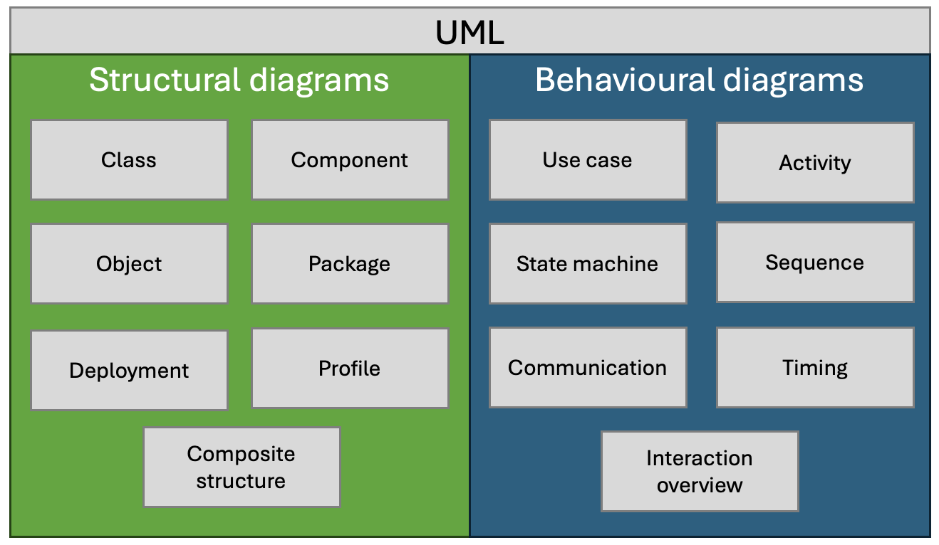
In an Agile project, UML fits seamlessly into the iterative and incremental development lifecycle by providing a visual framework for planning, designing, and communicating complex software structures and behaviours. During the early stages, UML diagrams such as use case diagrams help capture and clarify user requirements, ensuring that the development team and stakeholders have a shared understanding of the project’s scope and goals. As the project progresses through sprints, class diagrams, sequence diagrams, and activity diagrams are used to design and document the system’s architecture and interactions, facilitating effective planning and implementation of user stories. UML’s flexibility allows for continuous refinement and adaptation of the models, aligning with Agile’s emphasis on responding to change and improving through iterative feedback. By integrating UML into Agile practices, teams can maintain a clear and organized design process, improve communication, and ensure that the evolving system meets both functional and non-functional requirements effectively.
This set of practical exercises does not aim to explain what each UML diagram type is for and how it is used - it is assumed that you already have some experience with the diagrams themselves. Instead, we will focus on the use of the StarUML modelling tool to create some example diagrams for a simple scenario.
2. Setting Up the Environment
First, you need to download and install StarUML using the instructions on the website.
As the website explains, users often confuse diagramming tools like Microsoft Visio with modelling tools like StarUML. It is important to understand that a diagram is not a model. A software model describes aspects of a software system such as structure, behaviour, or requirements and can be represented textually, mathematically, or visually. A diagram, on the other hand, is a visual representation of a software model, focusing on specific aspects like class hierarchy or object interaction. Diagrams consist of view elements that visually represent model elements. A model element has its own data and can be rendered in multiple view elements across different diagrams, ensuring changes to the model element are reflected in all corresponding diagrams.
Familiarise yourself with the StarUML interface and its main terminology including the terms
- Project
- Fragment
- Element
- Extension
3. Scenario
We will be modelling an online library management system where users can browse, borrow, and return books. The system has two main user roles: Librarian and Member. The database backend stores information about books, users, and transactions, while the user interface allows users to interact with the system.
User Roles
- Librarian: Manages the library’s inventory and oversees member activities.
- Member: Searches for books, borrows them, and returns them.
Classes
- User
- Attributes: userID, name, email, password
- Methods: login(), logout()
- Librarian (inherits from User)
- Attributes: employeeID
- Methods: addBook(), removeBook(), viewMemberActivity()
- Member (inherits from User)
- Attributes: memberID, borrowedBooks
- Methods: searchBook(), borrowBook(), returnBook()
- Book
- Attributes: bookID, title, author, ISBN, status
- Methods: updateStatus()
- Transaction
- Attributes: transactionID, bookID, memberID, borrowDate, returnDate
- Methods: recordTransaction()
Database Backend
- Tables: Users, Books, Transactions
- Relationships: Users to Transactions (one-to-many), Books to Transactions (one-to-many)
User Interface
- Librarian Interface
- Login/Logout
- Add/Remove Book
- View Member Activity
- Member Interface
- Login/Logout
- Search for Books
- Borrow Book
- Return Book
4. Set up a StarUML project
A project in StarUML is a container for a model. As you work through the modelling process, you will add detail to the model by adding diagrams to the project.
StarUML offers the opportunity to use structural templates for a project. For simplicity, however, we will be starting with an unstructured model which is the default when starting the application.
Give the project the name “Library management system” and save it to an appropriate location on your computer.
For more information, see the relevant part of the StarUML documentation.
5. Use Case Diagram
As a first step in elaborating the model, we will add a use case diagram. StarUML provides several options for doing this, but it is important to select the containing item in the navigator first. For this reason, it is a good idea to get used to right-clicking the appropriate item and using the popup menu to create the diagram as shown in Fig. 2.
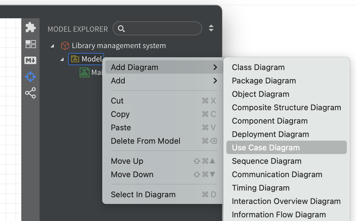
Your diagram should contain the following elements:
- Actors: Librarian, Member
- Use Cases: Login, Add Book, Remove Book, View Member Activity, Search Book, Borrow Book, Return Book
For more information, see the relevant part of the StarUML documentation.
Remember to save your diagram after each modification.
6. Class Diagram
Next, add a class diagram to the model that includes the following information:
- Classes: User, Librarian, Member, Book, Transaction
- Relationships: Inheritance (Librarian and Member inherit from User), Associations (User to Transaction, Book to Transaction)
Note that the StarUML menus are context-sensitive. You may need to close your use case diagram before the option to create a class diagram is available.
Remember to create your new diagram by right-clicking the model in the navigator. If you forget, you can either close the model without saving and re-open it, or delete the unwanted elements from the navigator.
For more information, see the relevant part of the StarUML documentation.
7. Sequence Diagrams
The next stage is to add sequence diagrams that describe two example processes as specified below.
- Member Borrows a Book
- Sequence: Member searches for a book, selects a book, system checks availability, records transaction, updates book status.
- Librarian Adds a Book
- Sequence: Librarian logs in, enters book details, system updates book inventory.
For more information, see the relevant part of the StarUML documentation.
8. Activity Diagram
As a final example in this tutorial, we will add an activity diagram for the process of borrowing a book as described below.
- Member searches for a book
- Member selects a book
- System checks availability
-
if available
-
System records transaction
-
System updates book status
-
System confirms borrow action
-
-
otherwise
-
System displays unavailable message
-
Use swimlanes to separate the actions that are performed by the member from those performed by the system.
For more information, see the relevant part of the StarUML documentation.
9. Check your solution
StarUML can export the full model including the various diagrams as HTML pages. Compare your solution to the one available here.
You should find some differences since the online solution contains some additional information. In the next step, you will add the missing information.
10. Add more detail
Close any diagrams that you have open and save your work.
This part of the tutorial demonstrates the difference between a model and a diagram. In the first step, we will add some properties and methods to our classes; however, instead of updating the class diagram, we will add the details directly to each class using the navigator.
If you did not give your model elements names as you went along, you may want to do that now to make navigation easier. Then find the book class in the navigator and right-click on it. This will display a context menu as shown in Fig. 3. where you have options to add attributes (properties) and operations (methods).
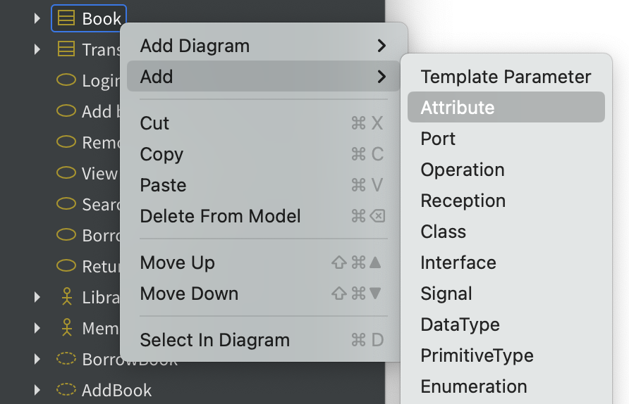
Add the following properties to your classes:
- Book
- id
- isbn
- title
- author
- status
- User
- id
- name
- password
-
Transaction
- id
- transactionDate
- transactionType
Note that a book may have more than one author.
Using a similar approach, add the following methods to your book class:
- getStatus
- setStatus
setStatus requires a parameter that represents the new book status. For this, we first need to add an enumeration called statusValues to the book class using the context menu.
Once added, use the context menu again to add three statuses:
- on_shelf
- on_load
- lost
Now we can use the enumeration to define a parameter for setStatus. Right-click on setStatus and select Add->Parameter from the context menu. One of the properties of the parameter is type which should be set to the name of the enumeration as shown in Fig. 4. You can use the magnifying glass icon to search for the enumeration in the model.
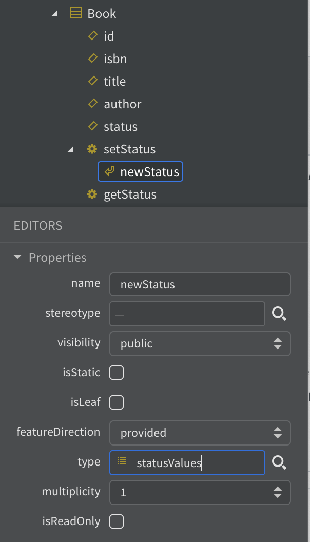
Now open the class diagram - you will see that the new information is included even though the diagram has not been edited. You may need to tidy up the layout a little.
Save your work and check your solution against the online version again. You should find that it is a better match.
You can create similar documentation from your own model by choosing File->Export->HTML Docs… from the menu.
11. Put the model to work
In this final stage, we will use the model to generate some C# code that can be used as the starting point for a development project. To do this, we will need to add an extension to StarUML.
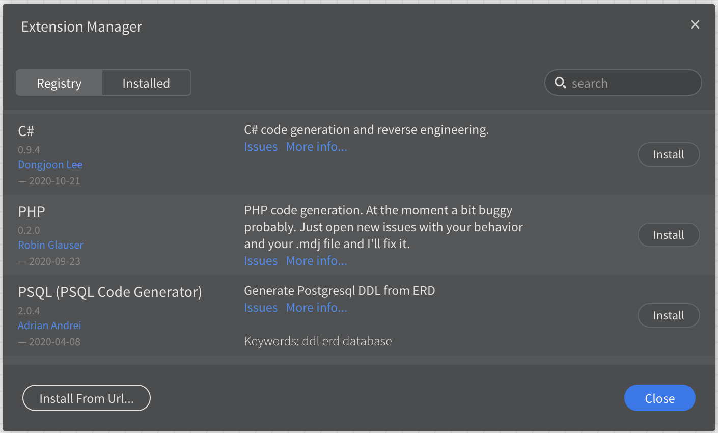
Open the extension manager from the Tools menu. Fin the extension called C# by Dongjoon Lee as shown in Fig. 5 and click Install.
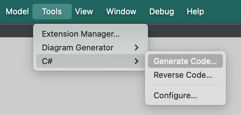
The extension adds some new options to the Tools menu as shown in Fig. 6. Select the Generate code… option.
Follow the prompts to generate your code and examine the results with a text editor. You will see that there is still a lot of detail to fill in, but the files that have been created provide a structure that corresponds to your model. Using this structure helps to avoid overlooking details as you start the implementation.